
In this lab you will learn how to control the motors of the robot and read out their positions, how to solve the inverse kinematics in order to move to specific coordinate points, and how to move between points on defined paths. With this knowledge, you can design and implement your own robotics application.
Orientation
Motivation
Robots are used in all areas of industry today - whether in the production of goods, the manipulation of parts, or in the field of sorting and packaging. Therefore basic knowledge of industrial robotics (kinematics of robots, basics of programming) is very important. With the help of a morobot, laboratory exercises and experiments can easily be performed at your own desk. This laboratory deals with the SCARA robot, which has two rotary and one linear moving axis, to which an end effector (gripper, suction cup, magnet, ...) can be attached. After you learn how to control the morobot and calculate its inverse kinematics in the basics, you program the robot to move to defined positions and to move between points on predefined paths. Then you can think of and program your own application.
Requirements
- Knowledge of the development environment Arduino
- Basic knowledge of electronics
- Basic knowledge of servo motors
- Trigonometry
Learning Objectives
After completing the online laboratory, you will be able to…
- … control servo motors over Arduino boards.
- … calculate and implement inverse kinematics required for the control of robots
- … set defined cartesian coordinates with the robot.
- … move objects with the morobot.
Recommended Reading
The laboratory exercise uses smart servo motors of the Smart Servo MS-12A series, whose documentation can be found HERE. To use the servo motors in Arduino sketches, the corresponding Arduino library exists HERE and HERE. This library contains example sketches and descriptions of the implemented functions. For the calculation of the motor angles depending on cartesian coordinates, please refer to the theory of inverse kinematics. Further details on inverse kinematics can be found in the module Basics. Information about the mechanical and electrical design and programming in the Arduino development environment can be found in the document morobot_gettingstarted_en.pdf.
Guide
The laboratory takes between 90 and 120 minutes The concrete duration depends on the individual learning progress.
The following activities are expected of you:- In the module Basics
- you read up on and develop an understanding of the necessary theory.
- In the module Application
- you will be given various tasks.
- In the module Considerations
- you get a short summary of the results.
Basics
Getting Robot
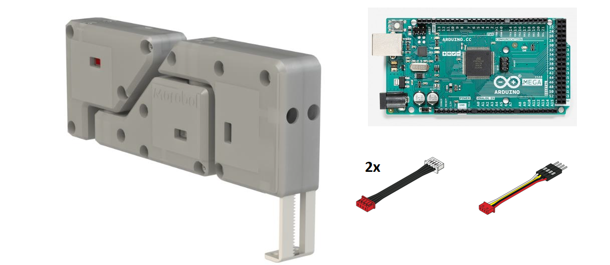
To carry out this laboratory, a morobot, an microcontroller, and connectors are required.
This set can be borrowed from the UAS Technikum Wien.
If you use your own microcontroller, please note that the application Coordinates by User-Input can only be performed with boards with at least two serial interfaces.
An Arduino Mega or ESP32 is recommended for this application.
The morobot itself can also be manufactured and assembled independently.
For this purpose, the FH Technikum Wien provides the component drawings, which can be produced using 3D printing technology.
In both cases please contact the ENGINE team via E-Mail.
Documentation
As already described, an introduction for the usage of the morobot is available in the document morobot_gettingstarted_en.pdf.
To test the configuration you can use the following Arduino sketch.
The example moves the first two axes by 20° to the left and then to the right and moves the linear axis out and back in again.
At the end of the sequence, the built-in LED on the Arduino will light up briefly.
#include <SoftwareSerial.h>
#include "MeAuriga.h"

MeSmartServo MyRobot(PORT5);
uint8_t inc=0;

void setup() {
    MyRobot.begin(115200);
    delay(5);
    MyRobot.assignDevIdRequest();
    delay(50);
    pinMode(LED_BUILTIN, OUTPUT);
}

void loop() {
switch (inc)
    {
    case 1:
        MyRobot.move(1, -200, 1);
        inc = 0;
        break;
    case 2:
        MyRobot.move(2, 20, 1);
        break;
    case 3:
        MyRobot.move(3, 100, 1);
        break;
    case 4:
        MyRobot.move(1, -20, 1);
        break;
    case 5:
        MyRobot.move(2, -20, 1);
        break;
    case 6:
        MyRobot.move(3, -100, 1);
        break;
    default:
        inc = 0;
        digitalWrite(LED_BUILTIN, !digitalRead(LED_BUILTIN));
        delay(500);
        digitalWrite(LED_BUILTIN, !digitalRead(LED_BUILTIN));
        break;
    }
    delay(2000);
    inc++;
    Serial.println(inc);
}
Inverse Kinematics
The forward kinematics calculates the positions of the end effector by using given joint angles of the robot.
The inverse kinematics is the counterpart of the forward kinematics.
So the inverse kinematics uses given positions to determine the joint angles to be set.
This is the necessary basis for robots to approach target coordinates.
The degrees of freedom of the kinematic chain, which increase with the number of joints, play an important role here.
Thus it is usually possible to approach a certain position by several different robot configurations.
The achievable accuracy of the position to be approached depends largely on the hardware used.
In the case of the morobot the built-in servo motors have a resolution of 1°.
Additionally, the accuracy of the morobot decreases due to the existing mechanical clearance of the assembly.
In this laboratory, the use of trigonometric functions is sufficient to complete it successfully.
This means that complex solution approaches, such as the introduction of the Jacobian matrix or the application of numerical methods, are not required.
Application
In the previous section, the basics have been described in order to solve the following tasks on the morobot. The exercise descriptions are available in the respective subchapters.
Calculation of the Inverse Kinematics
Before specific tasks can be performed with the morobot, it must be ensured that the end effector can reach certain positions.
Since normally coordinates are given, the inverse kinematics of the morobot must be calculated in this task.
Thus the joint angles are calculated by specifying cartesian coordinates.
Since the morobot has two joints, two robot configurations are usually possible to set a position.
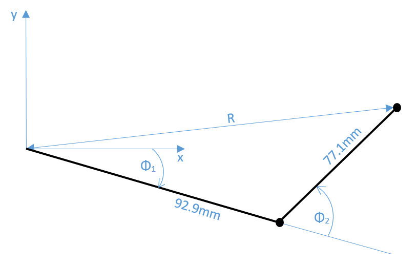
However, this does not have to be considered here.The dimensions of the morobot can be taken from the following figure. The kinematic limits can also be derived from the figure. Please note the minimum and maximum adjustable coordinates of the morobot. To avoid destroying the hardware, the two joint angles may only be in the range -90° < Φi < 90°.
Note: You can use the cosine theorem to calculate the inverse kinematics.
Task overview:
- Calculate Φ1 and Φ2 as functions of the given arm lengths!
- Define the working area of the morobot via the radius R!
Arduino Implementation
In this task the previously determined inverse kinematics shall be implemented in an Arduino sketch to approach certain coordinates.
The coordinates can be chosen freely and shall be approached by the end effector one after another.
You can decide whether the process is executed only once (implementation in setup()) or repeated (implementation in loop()).
If specified coordinates are not within the working range of the morobot, the setting of these configurations in the Arduino sketch should be prevented..
Coordinates by User-Input
Now that the calculation of inverse kinematics is implemented in the Arduino sketch, the sketch shall be extended to allow users to enter coordinates via serial communication.
For this purpose, the serial monitor of the Arduino development environment shall be used.
Therefore, a permanent USB connection to the computer is assumed.
The sketch should make it possible to pass single xy-coordinates to the Arduino board via the serial monitor, which are then approached by the morobot.
This process is to be carried out endlessly, whereby entered xy-coordinates must be intercepted outside the workspace.
The following figure shows an exemplary program flow on the serial monitor.
Save Robot Positions
This task shall demonstrate another useful possibility of smart servos.
The smart servos allow to read out current angular positions.
Use this feature by manually setting three robot positions, which are read by the Arduino board and stored in variables.
After the positions have been saved, they should be approached one after the other, automatically and in a continuous loop.
The following figure shows an example of a program sequence on the serial monitor.
In this example, exactly three positions are stored, which can of course be adjusted as desired. As a program extension, no exact number of positions can be given, but after setting all desired positions, the program is informed by a UserInput that all positions have been set. The sample solution of the extension program including an example video can be downloaded HERE.
Feel Free!
Now you can define your own applications for the morobot.
Inspirations:
- control via the serial interface
- moving objects
- drawing of certain shapes
- …
Considerations
After completing the online laboratory, you are able to… …
- … calculate inverse kinematics for controlling robot arms.
- … control servo motors via Arduino boards.
- … control a robot directly via serial communication.
- … read out and store current angular positions of smart servo motors.
Self-Evaluation
Below you find questions, which you can solve after succeeding the online laboratory. The solutions are shown by clicking on the questions.
What are inverse kinematics used for?
It is the counterpart to forward kinematics and allows the calculation of the required joint angles of robot arms to reach given positions. The required angles are calculated from coordinates (e.g. cartesian).
What do you have to consider with inverse kinematics?
Depending on the degrees of freedom of a kinematic chain, coordinates can be achieved by different link angle settings.
What has to be considered in programs when calculating joint angles to be set?
As a protection against component destruction, the working area of the robot should be calculated, thus excluding coordinates that cannot be reached.
How can users communicate with the Arduino board during operation with smart servo motors?
The communication between user and Arduino board can be done via a serial interface. To use this, the board must have at least two serial ports, since one is needed for communication with the servo motors.
Take-Home-Messages
- The inverse kinematics of a robot is needed to calculate which joint angles are necessary to reach a given coordinate position.
- By excluding non-adjustable robot configurations, component destruction is prevented, which is why a permissible work area should be defined.
- Trigonometric functions facilitate the calculation of the inverse kinematics of short joint chains.
- Smart servo motors allow the readout of end effector positions, which can then be saved and repeatedly adjusted.
- An additional advantage of smart servo motors is the control of several motors with only one serial interface.
Links and Literature
Here you find a summary of the linked literature.
- Smart Servo MS-12a
- Smart Servo MS-12a Arduino library
- All Makeblock Arduino libraries
- Inverse kinematics
- morobot_gettingstarted_en.pdf