
Ball Maze
The ball maze consists of a labyrinth plate, which has been created by additive manufacturing and is positioned by two electric linear drives. In the center of the ball labyrinth is a rotatable bridge, which has also been produced by additive manufacturing and is positioned by an electric rotary drive. The position of the metal ball is determined by four induction sensors. The rotation of the labyrinth plate in the plane is read by a tilt sensor. With the help of an additional camera the top view of the ball maze is transmitted via OPC UA.In this online lab, you will learn how to control the labyrinth, detect the ball position, and let it navigate automatically through the maze.
Orientation
Motivation
The ball maze offers a playful access to the world of complex image recognition and the control of a mechatronic system. Many industrial systems today use image processing algorithms to collect and process data. For this reason, knowledge of this matter is essential. After you have connected to the ball labyrinth and can manipulate variable values, the exercise guides you through manually moving the labyrinth. Then you will perform a camera calibration, write an algorithm to detect the ball position, which allows the automatic movement through the maze by means of a simple control algorithm.
Requirements
- Knowledge of a programming language is necessary
- Basic knowledge of the industry protocol OPC UA (online exercise OPC UA)
- Basic knowledge of a image processing library (here OpenCV is used)
- Basic knowledge of control engineering
- An already configured programing environment
Learning Objectives
After completing the online laboratory, you will be able to…
- … read out the sensors of a mechatronic system and address the actuators.
- … read images and calcuate a calibration matrix based on these images.
- … find known objects in an image.
- … to carry out a setpoint/actual value comparison in the sense of a control algorithm to guide the ball through the labyrinth autonomosly.
- … to work with an external robot using the OPC UA protocol.
Recommended Reading
Since knowledge of the industry protocol OPC UA is assumed here, the online exercise OPC UA should be completed beforehand.
Guide
The laboratory takes between 90 and 120 minutes. The concrete duration depends on the individual learning progress.
The following activities are expected of you:- In the module Basics
- you read up on and develop an understanding of the necessary theory.
- In the module Application
- you will be given various tasks.
- In the module Considerations
- you get a short summary of the results.
Basics
Recommended Software
The programing language Python is recommended, since required functions are already available in libraries.
The Python libraries are listed below.
Other programing languages can also be used.
In addition to the Python libraries the software UA Expert from Unified Automation is recommended.
This is an OPC UA client which visualizes the server structure and the nodes of the OPC UA sever.
Access Information
In order to get access to this online laboratory, following information are required:
- Namespace-URI: opc.tcp://engine.ie.technikum-wien.at/BallMaze
- Root-Node des Kugellabyrinths: ns=1;s=Ballmaze
- Benutzername: ballmaze
Communication (OPC UA)
The communication basics are explained HERE. Note, that an interaction with the hardware is only possible with the usage of the communication protocol OPC UA.
Moving the ball maze
The ball maze is controlled from the outside by an OPC UA server, which forwards the commands to an Arduino Mega to control the robot using G-code. Since only an OPC UA connection is available for these exercises, an OPC UA client is required. This client must be able to read and write to different nodes and their values from the server. This is done using methods that are implemented on the server. Each value has a unique identification number with which this value can be read and written. For the following programming the OPC UA library of Python is used.
As a first step it is recommended to take a closer look at the OPC UA server of the ball maze. The best way to do this is to use the program UA Expert from Unified Automation. This is an OPC UA client that supports searching the namespace and clearly displays all nodes and methods. It is also possible to get a live video stream from the maze's camera.
For the actual reading and writing of values a connection to the server must be established at the beginning. This connection is authenticated with a user name and password. To log on to the server, the functions Client() and connect() are used in a Python script. In the function Client() username, password, hostname and port are passed to establish the connection with the function connect(). Afterwards the namespace of the ballmaze can be selected with the function get_namespace_index() to access the nodes afterwards. The function get_node() can be used to access the nodes by specifying the namespace and the identifier of the corresponding node. With the function get_value() it is possible to read the value contained in the node. If the OPC UA Server allows it, values of a node can also be written directly with set_value(). Normally and to ensure that not invalid values are written to a node, the write operation is done by a method and values are not directly writable. A method can be used to check the value to be changed and discarded if it is invalid.
To finally call a method, the function call_method() is used. This function can be used to read values from the method as well as to write them into the method to finally control the robot. The last step is to close the connection to the server with the function disconnect(). Some OPC UA servers deny multiple parallel connections to avoid conflicts. If the connection has not been closed properly, it must be closed manually on the server.
Camera Calibration
Every camera has a certain amount of distortion and interference. This is due to the curvature of the lens and the construction of a camera. For exact measuring of lengths or for the exact determination of a position in the camera image it is therefore important to calibrate the camera first. In this step the camera is suppressed and calibrated to a defined pattern. There are a number of different calibration procedures, but in this exercise you will work with a checkerboard pattern. The result of such a process is a camera matrix that describes exactly the unique distortion and interference of the camera used. Thus it is then possible to measure exact distances even with only one camera.
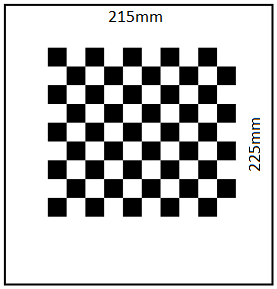
There are several steps in a camera calibration that are necessary to get a calibrated image that is free of interference. For the calibration a checkerboard pattern is used, which first has to be photographed with the camera from different positions and orientations. The following figure shows a chessboard with a working area. The dimensions of the calibration object are as follows:
- width of the border: 215mm
- height of the border: 225mm
- number of chessboard squares: 10x9
- length of chessboard square: 15mm
Since the ball maze only has fixed cameras in normal operation, various photos are provided. These can be downloaded HIER. The first step is to find out which of the photos are suitable or unsuitable for calibration. Only photos with sufficient exposure, sharpness and contrast, as well as photos that contain a checkerboard pattern of the correct dimension at all, are allowed. With the function cv2.findChessboardCorners() every single photo can be checked for a checkerboard pattern of the correct dimension. It is important that the function can only work with images in grayscale. It should also be mentioned that all images to be checked should have the same resolution, i.e. also from the same camera, with the same settings. If this is not the case, the function cv2.findChessboardCorners() is not executed correctly. It is absolutely necessary to check the images for their resolution before. With the functions image.get(cv2.CAP_PROP_FRAME_WIDTH) and image.get(cv2.CAP_PROP_FRAME_HEIGHT) it is possible to read out the width and height of each scanned image. So every value can be stored and compared with values of other images.
As soon as in the first step edges of the chessboard have been recognized in an image, they must be stored in a variable. In addition so-called image and object points must be defined. The image-points indicate the pixel value of the found edge of the chessboard in the respective image. When an image is loaded into Python, it is available as a matrix. The number of vertical matrix entries corresponds to the height of the image in pixels, the number of horizontal entries to the width. This allows to determine where exactly on the image an edge of the chessboard is located. The object points, on the other hand, describe where the edge of the chessboard is located in a three-dimensional coordinate system in reality. For example, it is possible to determine the distance between the edges and the size of the chessboard tiles. This makes it possible to further determine the position of objects in space.
Once the image and object points have been declared, these points must be assigned to each image in which edges were detected. The later calibration process is only successful if enough images have been provided with image and object points. For a calibration at least ten valid images should be used. In theory, a camera calibration works with only two images taken from different angles. However, the more images are used, the better the process works.
The function cv2.cornerSubPix() refines the specific edges of the chessboard in each individual image. This improved representation of the real corners of a field in the chessboard is necessary to ensure the accuracy of the subsequent calibration. With the refined edges, the individual points can now also be output graphically for illustration purposes.
The last step is the actual camera calibration. The function cv2.calibrateCamera() finally returns a camera matrix and a distortion coefficient. These should definitely be saved in a file to be able to use them again in further exercises and to get exact results.
Recognizing Objects
In order to track the ball position in the labyrinth and to enable controlling the system, the position of the ball must be detected. There are several methods to detect closed objects. In this exercise you work with a so-called Hough Transformation. This can be used for circle and line detection.
At the beginning of this task an image must be loaded into the program.
In the first step of the this task, circles are to be detected.
These are detected by means of Hough Transformation.
The Hough Transformation is used to detect geometrically known shapes.
Therefore images are transformed into the Hough space.
Every point that could lie on an edge (straight line) is first called the intersection of infinitely many straight lines.
In the Hough space, points lying on a common straight line are then clustered.
This accumulation describes a line or edge in the real image.
Note that the Hough algorithm can only work with images in grayscale.
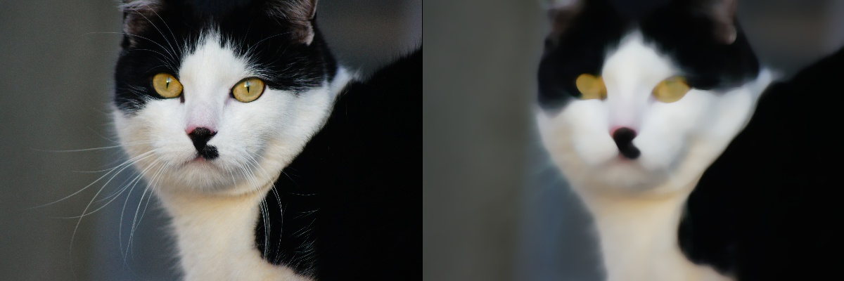
To be able to detect circles properly, it is necessary to modify the image with a blur filter.
This filter ensures that edges of the image are blurred and only circles that are actually circles are recognized.
With the function cv2.medianBlur() such an effect can be achieved.
In the following figure you can see a symbol photo which makes this function clear.
It can be clearly seen that the edges of the symbol image have been blurred.
In the next step, circles can be detected and stored in a variable using the function cv2.HoughCircles() contained in OpenCV. For debugging the function cv2.circle() it is helpful to graphically display the detected circles in the image.
Application
In the previous section, the basics have been described in order to solve the following tasks on the Ball Maze.
Establishing a connection and manipulating variables
Connect to the ball maze. Instructions for this can be found in the OPC UA online exercise. The access information can be found in the basic chapter of this lab.
It is recommended to first establish a connection using UA Expert and to study the structure of the server. With the help of this program you can also read out sensor values, view the camera stream and move the actuators to target positions. Then write a simple command line program that controls all actuators, first separately and then simultaneously. Output all sensor values and the camera image after each movement. You can see how the movements influence the measured values (e.g. rotation around the different axes of the ball labyrinth).
Manually run through the ball maze
Extend your program from the first exercise so that the camera image and sensor values are displayed as a continuous stream. Implement a command line control: By pressing different keys on the keyboard you should control the ball maze (e.g. control the inclination around the axes using the arrow keys). With the help of this program you should be able to drive through the labyrinth manually.
Calibrating the camera
In order to have a program track the ball in the labyrinth, a camera calibration is necessary in the next step. A detailed exercise description in PDF format for performing the camera calibration can be downloaded HERE. The exercise refers to the Puzzlebot, but can be performed in the exact same way for the ball maze. The necessary images for the camera calibration can be downloaded HERE.
Detecting the ball position
Implement an algorithm that calculates the ball position from the images of the camera stream. To do this, use the camera matrix determined in the previous step to deskew the images. There are several possibilities to detect the ball (e.g. shape, color). Test different methods to detect the ball position as reliably as possible. Show the position of the ball in the image by displaying a colored circle at the ball position. Also display the coordinates of the center of the ball.
Implementing the control algorithm
To let the ball labyrinth run through the maze automatically, you must adapt and merge the functions implemented in the previous steps.
There are numerous possibilities to solve the task of automatically traversing the labyrinth using control technology.
In this exercise a relatively simple procedure is proposed:
Program a state machine that, depending on the position of the ball, will address the actuators to move the ball into the next state.
Your states are determined by the position of the ball.
Note that the position of the ball can vary slightly, so you should not check for exact values but allow a certain threshold.
For example, you start in State_0 (starting position) and want the ball to go to State_1.
You must control the actuators in such a way that the labyrinth plate tilts strongly in one direction and weakly in the other direction.
Once the ball reaches State_1, you need control commands to get to State_2, and so on.
You must check whether the next state is really reached and if not, set further actions.
Also use the binary sensors of the ball maze to check the states.
You can determine the control commands with the help of the program for manually passing through the labyrinth.
The positions for defining your states are provided by the program for recognizing the ball position.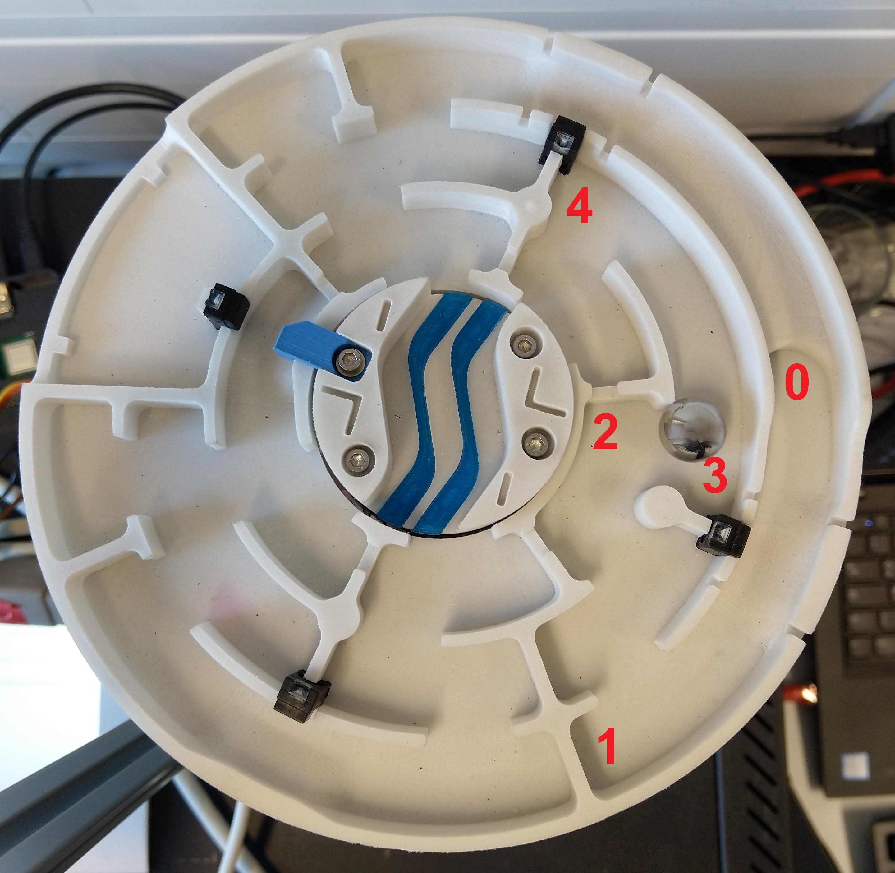
Considerations
After completing the online laboratory, you are able to…
- … read out the sensors of a mechatronic system and address the actuators.
- … read images and calcuate a calibration matrix based on these images.
- … find known objects in an image.
- … to carry out a setpoint/actual value comparison in the sense of a control algorithm to guide the ball through the labyrinth autonomosly.
- … to work with an external robot using the OPC UA protocol.
Self-Evaluation
Below you find questions, which you can solve after succeeding the online laboratory. The solutions are shown by clicking on the questions.
What is the function cv2.findChessboardCorners() used for?
With this function images are checked for a checkerboard pattern with a certain dimension. This way it can be determined whether the images are suitable for camera calibration.
What is the Hough Transform for?
It allows to recognize known geometries such as circles in images. The OpenCV Python library already contains functions to identify certain geometries. For example, the function cv2.HoughCircles is used to recognize circles.
Take-Home-Messages
- A camera calibration is necessary to calculate lengths correctly. Therefore, images with known dimensions and geometries are needed.
- When using functions of the OpenCV Python library, please note that some functions can only work with grayscale images.
- To identify objects by color recognition, it often helps to convert images to HSV color space. This is done with the function cv2.cvtColor from the OpenCV Python library.
Links and Literature
Here you find a summary of the linked literature.
- online exercise OPC UA
- image processing software OpenCV
- OPC UA Python library
- OpenCV Python library
- Pillow Python library (with Image Modul)
- UA Expert